Replacing our Radiator Surge Tank- 2003 Freightliner XC

 Odometer 77,861 miles

Trip Meter- 0 miles

Spoiler alert- This is a tech session, so if you’re looking for travel and adventure- skip this post and read the next 😊

I have used this platform before to talk about mechanical issues that have happened to our motorhome, and it has sometimes helped others that have the same issues.  I have been the beneficiary of many blogs and online video how-tos.  This is my way of paying back the universe.

Picture #1  Surge tank on top of radiator

If you have a Freightliner XC chassis built around 2000 and have a caterpillar 3126 engine, you are familiar with this view of the rear engine compartment of your coach.  The tank on top of the radiator is the surge (or overflow) container that stores coolant that expands when the engine heats up, and returns the coolant to the radiator when the engine cools down.  Unfortunately the tank breaks down in sunlight and starts to crack, and crumble, and leak.
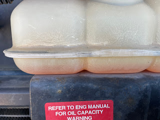
Picture #2. Cracks in surge tank

Here’s a closeup of what our tank looked like.  The cracks have been there for several years now and that have finally cracked all the way through, allowing coolant to leak out. We did this repair ten years ago for what we thought would be the last time 😏.

It did occur to me at that time that I should do something to protect the tank from uv rays (sunlight), but I was convinced that sunlight didn’t really get that far into my engine bay. Well.. surprise!  My naivety means that we get to do this again.


The new tank was available at the Freightliner dealer near me in Phoenix, AZ.  The price at the time of this posting (2024) was $169.00. For owners of diesel pusher motor homes, getting to the engine usually means removing the bedding and the bed platform, and the engine covers. 

Picture #3. Exposing the engine covers in an ‘03 Itasca diesel pusher 

The surge tank is held onto the radiator with four 9/16” bolts and nuts.  And they pretty darned hard to get at.

Picture #4  Four attachment bolts and nuts 9/16”

At location #4 in the picture above, some have opted to take a reciprocating saw and cut the tank loose, because it is very challenging to get at. The other three can be accessed from the engine side (inside the coach), albeit they are still no fun and require much contortion.  

Picture #5   Mounting bolt on the passenger side rear of the tank

We (Joan and I) opted to un-bolt the old tank, mostly to keep from splashing coolant all over our driveway if we used a reciprocating saw to cut the tank out.  If you’re going to put this bolt back into the new tank- you might as well learn how to get at it.  (Some have opted to leave it out of the new tank- you decide). 
To start, we took the oil dipstick hanger loose and removed the dipstick, putting the dipstick somewhere safe for the moment.  We were then able to pull the dipstick tube back into the engine bay and out of our way. (It’s a flexible plastic tube).

Picture #6. Removing Oil filler 
Next, we took the oil fill tube and twist/pulled it out of the gasketed connection in the engine bay.  See photo to the right.  Take time now and stuff a clean paper towel, or rag, in the open end of the fill tube and dipstick tube to keep foreign material out of your oil.

Doing these last two steps gives one enough room to  get a ratchet on the head of the bolt from the inside of the engine bay.  This is where, at least on our coach set-up, the contortion part comes into play. (One of several parts).  Unfortunately I didn’t get a photo of my body posture, but here’s what I had to do:

  • Since I am right handed, I kneeled beside the bed pedestal/ engine cover on the passenger side, facing the rear. (picture #3 above)
  • Reached in with my right hand, into the space created by the removal of the dipstick and oil fill.


Picture #7  Finding the rear most passenger side mounting bolt from the bedroom side
  • First I felt with fingertips to get a feel for where I had to get the ratchet on the bolt head.  The bolt goes horizontally through the plastic tank mount then, through a hole in the vertical steel of the tank platform. (Picture #7 above). I am close to 6 foot tall and I can just barely reach this area with my right arm fully extended and head turned sideways and pressed tightly onto the top of the engine deck lid.  One of the contortions I mentioned.
  • Next I withdrew my hand and went back in, this time with a 1/4” drive ratchet and a 9/16” socket.  To get the socket on the bolt you have to be nearly vertical with the ratchet (remember the webs on the plastic tank.  The plastic webs also prevent your turning the ratchet in a very big arc (maybe 10 degrees of movement)

Picture # 8. Rear most passenger side through bolt on talk mount.
  • Here you need an assistant on the outside to hold the nut.  The bolt on my coach is so close to the sidewall of the engine compartment that I cannot get a box end wrench on it- so an open end wrench is what I used.  The assistant can move the wrench up and down to back off the nut while you hold the ratchet on the other end- or you can do the reverse and see if you can turn the bolt with ratchet while the assistant holds.  As you loosen the nut, the bolt could be pulled back enough to get the box end wrench on the nut if you want to stop to do this.  It may prevent you from dropping the nut as it comes loose.  With patience you can do this!
  • The bolt goes through a flat metal strap the is the hanger for the oil fill tube below.  (Picture #5) Your assistant may need to lift a little on this hanger strap to allow you to withdraw the bolt from the mount.
Picture #9.  Accessing the forward passenger side mounting bolt
  • Okay, if you got this far, congratulations!  Only 3 bolts to go.  Next, I tackled the bolt just forward of the first one, on the same side of the tank.  Working from the bedroom side again (as you will for all of them) you’ll need two wrenches one to hold the nut and one to turn the bolt- hard, but not impossible.
Picture #10   The two driver’s side mounting bolts

The bolts on the driver’s side of the tank are at least visible.  With a combination of wrenches or vice grips remove these two.  The bolts are inserted vertically- bolt on the top, down through tank, and through platform to the nut.

I waited until the tank was loose to start removing the hoses, that way I could move it into a more advantageous position to get at the pinch clips on each.  Here’s what I did:
  • First I removed the filler cap and the overflow hose on the rear (exterior) side of tank
Picture #11   Remove all hoses and the level sensor from old tank
  • Depending on how much coolant is left in your old tank and, where you want that to go, you may want to rig a catchment ( I did this) and remove the lower return hose on the bedroom side of the tank.  (Outflow in picture above)  I was able to get a plastic 1 gallon juice bottle in the fan area and tip the coolant (mostly) into the bottle.  Unfortunately, you cannot simply insert a small hose and pump out the coolant (I tried this first) as the interior of the tank is a honey comb of plastic dividers.  So the messy way, was the only way.
Picture #12  Hose connection at inflow ports
  • Next I removed the two smaller hoses on the top of the tank.  With the overflow hose removed, I could now pull the tank inwards to the engine bay and get pliers on the retainers and work the hoses off.  I have no idea if the routing is important, (which hose to which port) so I marked one hose with red tape to get them oriented the same way on the new tank.
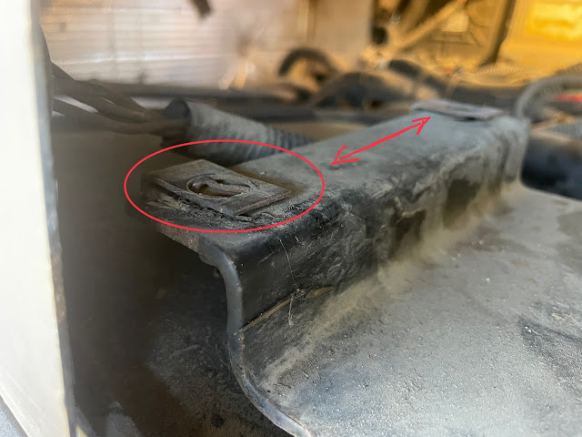
Success!  The old tank is out.  Now if you want to make the installation easier, you can do what I did on my coach.
Picture #13   Author has added clip nuts to tank mount


I added some 9/16” clip nuts (or cage nuts) to the radiator bracket, which allows me to bolt the tank in without fiddling with the nut on the back side.  The clip holds the nut in place for you.  The rear bolt that also holds the strap hanger for the oil fill is the only exception- at least I couldn’t figure out how.  Pick up some at your auto parts store.  Now you are ready to install the new tank.

Picture #14  swapping the coolant level sensor from old tank to new

Now is a good time to remove the coolant level sensor from the old tank, and assuming it was still working in the old setup, change it to the new tank.  Use the thread sealer of your choice to coat the threads.
Picture #15  Installing the new tank

Slide the new tank in from the engine bay in the coach.  Hook up all the hoses while you can still wiggle the tank around.  Fiddle with placement until the wedge shaped mount on the passenger side rear of tank drops down into the retainer as shown in photo #13 above.

I recommend starting the bolting with the hardest first, the passengers side rear.  This allows you to change the orientation of the tank a little to help getting the one bolt that isn’t going into a captured nut, started.

Picture #16  Start the installation with the hardest bolt to install- passenger rear


You will need your assistant again for this test of patience and communication.  You (or your assistant) will have to contort yourself again in the engine cowling, to insert the bolt into the rearmost mount while your opposite will steer the hanger bracket over the bolt as you push it through from the inside.

We found that taping the nut into the jaws of an open end wrench was the best solution to getting the nut re-installed on the bolt.  The outside member of the team maneuvers the nut onto the bolt as it is pushed through from the engine bay.  I was able to use my 1/4” ratchet and 9/16” socket to ratchet the bolt into the nut, a few clicks at a time, until tight.  The outside team member then pulls the wrench free.
If you were unable to find the clip nuts, or decided not to use them, similar techniques will help you get the rest of the bolts installed.  If you used clip nuts you’re probably done by now.

Picture #17   Re-install the dipstick tube and the oil fill tube 

All that is left to do now is to re-install the dipstick tube and the oil fill tube that was removed in the steps above.  The dipstick tube bracket mounts on a stud that is welded to the radiator cowl (7/16” nut).  The oil fill tube is a friction fit into the lower section of the fill tube at the gasketed joint in the engine bay


Picture #18   Completed operation.  New surge tank installed

Interesting to see that I put metal tape over the hydraulic fluid reservoir but not the coolant tank.  the hydraulic reservoir is still the original from 2003.  Guess that says something.  The surge tank is getting the UV blocking tape this time.

Now add coolant and test and check everything.

Note:  
Caterpillar’s engine owners manual says always use their own proprietary ELC (Extended Life Coolant) or another commercial product that has passed the Caterpillar EC-1 specifications.  The Cat coolant has special corrosion inhibitors, anti foaming agents, prevents formation of mineral deposits, and minimizes the  cavitation erosion of the cylinder liners.  Whatever you do- please don’t use green automobile antifreeze coolant.  I know enough to know I don’t know enough to go against Cat’s recommendations.

I hope this helps at least a few of my readers- it’s not pleasant, but it is do-able.

Your Traveling Friends

Jeff and Joan


Comments

Popular Posts